Table of Contents
Final project: Spectrum analyzer
A spectrum analyzer is useful for measuring the frequency content of a signal. If an oscilloscope plots v(t) versus t, a spectrum analyzer plots Sv(f) versus f where Sv(f) is the spectral density of v(t). In this project you'll build a simple spectrum analyzer. All the building blocks are familiar to you from previous experiments.
A basic realization of a spectrum analyzer is a very narrow bandpass filter that can be tuned to any frequency f0 followed by an signal strength(rms/envelope) detector. The output will be the strength of the input signal inside the passband of the bandpass filter. For very narrow bandwidths, there is very little variation in Sv(f) inside the filter's passband and what is measured (by an rms detector) corresponds to sqrt(Sv(f)*fb) where fb is the filter's bandwidth. It is very difficult to realize a tunable narrow bandpass filter and therefore, the signal is translated using a mixer driven by a variable frequency oscillator to a fixed frequency bandpass filter. In the system above, the input frequencies are in the range 0.5-5kHz(A lower limit of 0.1kHz enables ac coupling in the signal chain). These frequencies can be upconverted to 10kHz by mixing them with a local oscillator signal in the range 10.5-15kHz. A 10kHz filter is used to filter out the signal component and an envelope detector is used to measure the signal strength.
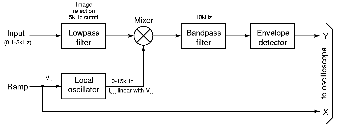 The block diagram of the spectrum analyzer is shown in the above figure. Each block is described briefly below. For a more detailed description of the spectrum analyzer, see the references at the end of the page.
- Low pass filter: This is used to reject the image frequencies-20.5-25kHz which also result in a 10kHz signal when mixed with 10.5-15kHz local oscillator. Use a fourth order Chebyshev filter realized as a cascade of two single opamp second order sections. See below for single opamp filter topologies.
- Mixer: This is used to mix the input signal with the local oscillator. Use an MC1496 double balanced modulator for this.
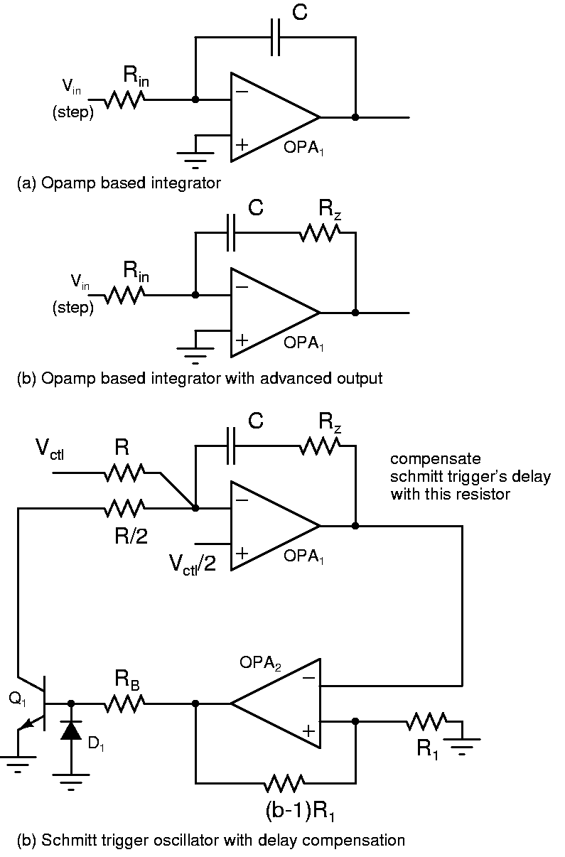
- Local oscillator: Output frequency varies from 10.5-15kHz as a linear function of the control voltage Vctl. To make an oscillator at 10.5-15kHz with a linear control using LM324 opamps, you'll need to compensate for the delay of the schmitt trigger(because of the slew rate). See below.
- Bandpass filter: Isolates the signal in a narrow band around 10kHz. Use a gm-C filter with a quality factor of 20 for this purpose.
- Envelope detector: This is used to measure the signal strength
The control voltage Vctl to the VCO is a measure of the frequency at which the signal strength is measured and forms the X co-ordinate of the display. The output of the envelope detector is the Y co-ordinate. By sweeping Vctl slowly, it is possible to measure the signal strength versus frequency. Plotting the envelope detector output versus Vctl on the oscilloscope in X-Y mode, one can get a display of the signal spectrum.
How to go about the project
This project is larger than any circuit you have built in the lab so far. It is next to impossible to get it to work with messy wiring, or with components spread all over the countryside. Difficulties with debugging such circuits must already be familiar to you from your experience in the lab. A clean approach from the beginning is the only way to get it to work. Also, do not wire the entire circuit and attempt to test it. Build each block and test it individually; Connect it to the previous block and test the combination, and so on. You can start working backwards from the envelope detector, of forwards from the front end low pass filter. Most blocks can be realized using a single IC and a few passive components enabling modularity in the design. Don't start on this project the day before the demonstration! Two weeks are allotted to the project so that you can thoroughly debug and demo the project. You should finish the assembly before coming to the lab session.
Evaluation
- You are expected to put together the blocks and make a complete system. No credit will be given for showing individual blocks. They have already been evaluated in earlier lab sessions.
- If you have backlogs in your experiments, and don't have a thorough knowledge of the experiments done so far, you are better off using these two weeks to finish off the experiments you didn't do before.
- Extra credit will be given for neat assembly/aesthetics; fully soldered projects; having a logarithmic output in addition to the linear one; Building your own sweep generator(the one that generates Vctl). However, the project must be successfully demonstrated for extra credits to be given. A project with lots of features that doesn't work will not be considered.
Sallen-Key filter
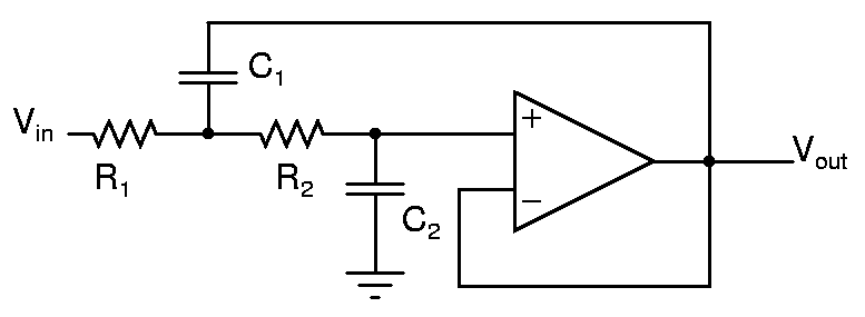
The topology of a Sallen-Key filter is shown above. A fourth order Chebyshev filter with a passband attenuation of 1dB can be made with a cascade of two second order sections with {fp=0.96f0, Q=3.56} and {fp=0.53f0, Q=0.78} where f0 is the desired passband edge(5kHz in this case).
Bandpass filter
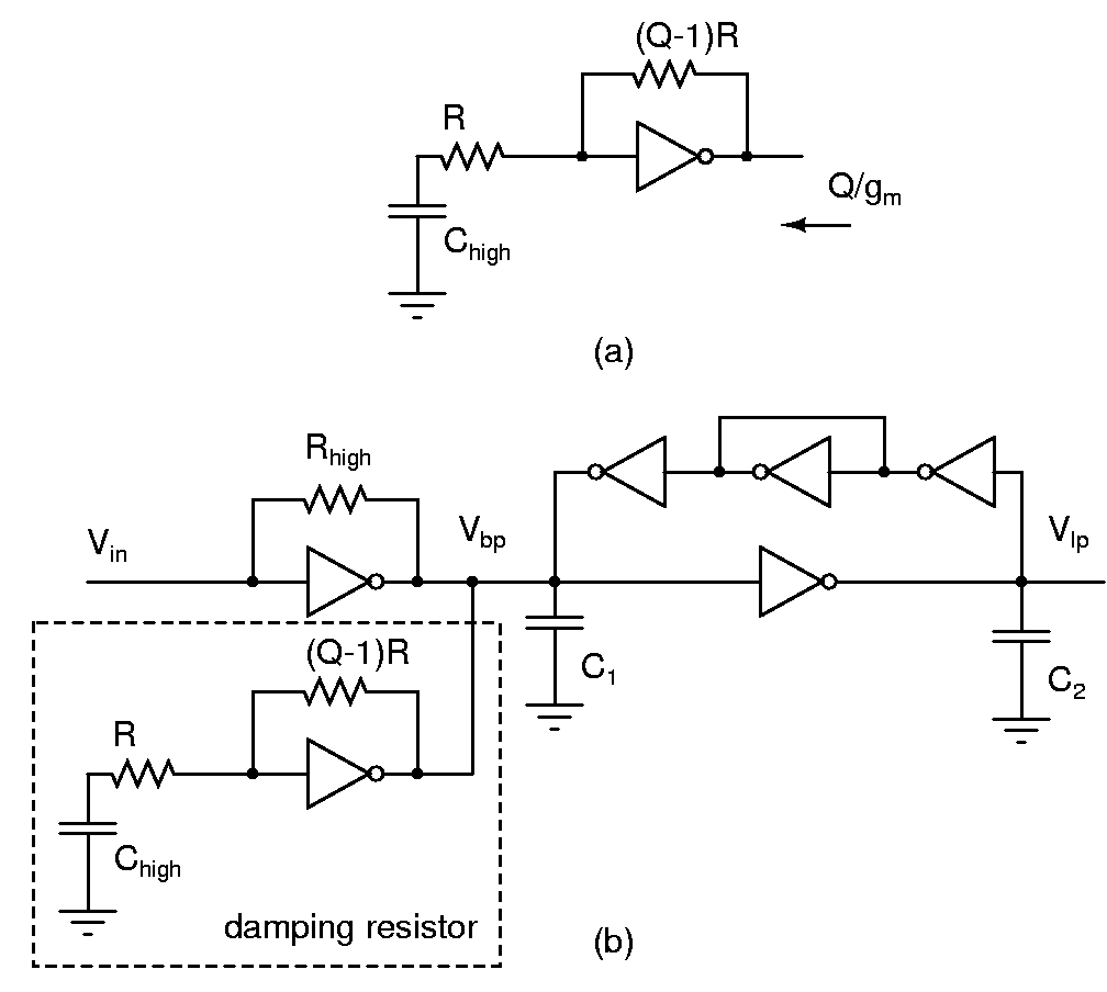
To get a high Q gm-C filter following what you built in this experiment, you will have to use a very high ratio between C1 and C2. The filter will not work properly under those circumstances. Use the above topology instead where you obtain a damping resistor of Q/gm. You can use equal capacitors in this case.
To start with, assemble the filter without the damping resistor(shown within dashed lines). The output conductances of the transconductors will provide damping. Verify that the filter is stable, and measure the bandwidth. If the bandwidth is about what you need, use it as is. Otherwise, add the damping resistor with a suitable Q.
Oscillator using transistors
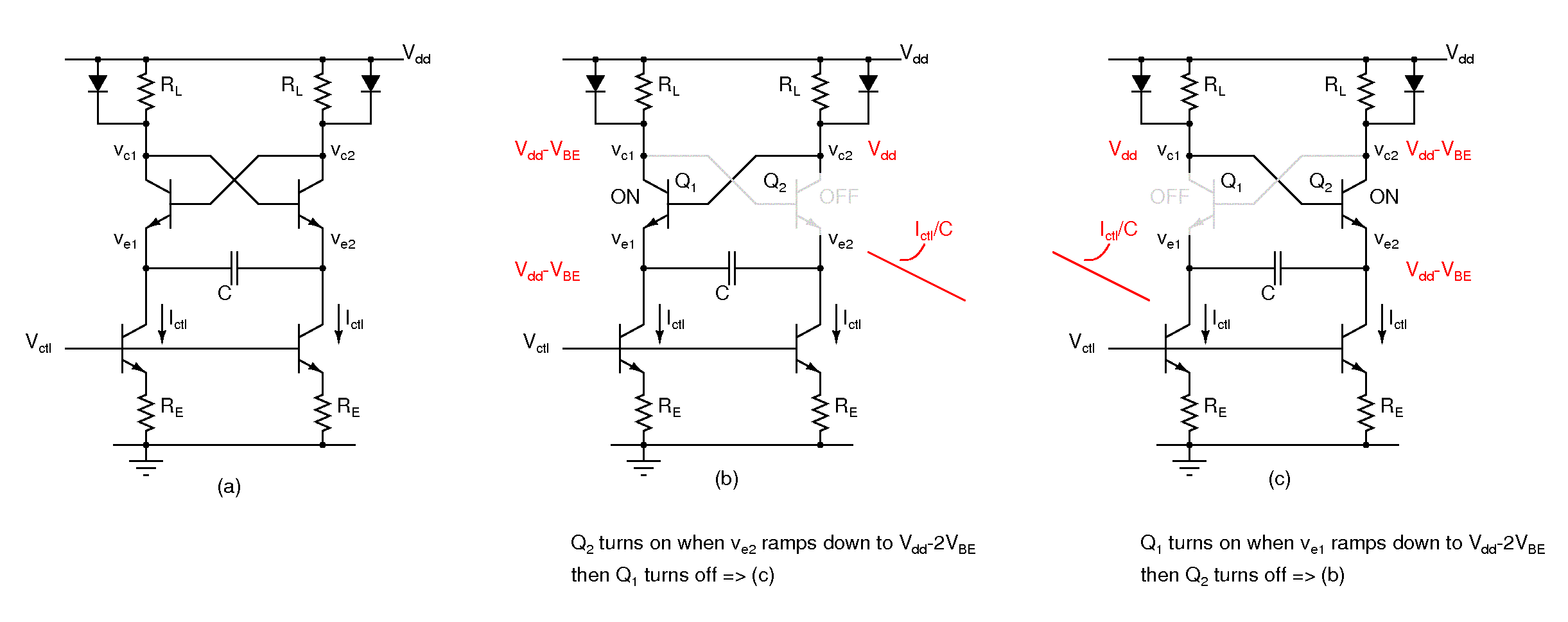
The oscillator using opamps seems to have problems at 10kHz and higher due to the low slew rate and bandwidth of LM324. Use the BJT oscillator below to overcome these limitations. The frequency of oscillation is given by Ictl/(4C*VBE). VBE ~ 0.65V. Fig. (a) shows the schematic and (b, c) show the two phases of oscillation. Choose Ictl*RL to be more than a diode drop(0.65V). The diodes in the collector prevent the collector voltage from going too low.
Opamp based oscillator with delay compensation
A resistor Rz in series with the integrating capacitor C advances the integrator output. Analyze the integrator with Rz for a step input and calculate the amount of advance. Calculate the amount of delay in the schmitt trigger because of the slew rate. Choose Rz so that this delay is cancelled.
References
- Spectrum analyzer basics Seminar slides from Agilent technologies
- Spectrum analysis basics Agilent technologies application note 150
