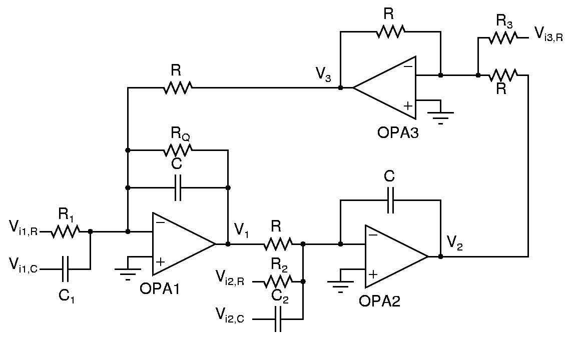
Opamp based universal filter
- The circuit below can have inputs Vi1,R, Vi1,C, Vi2,R, Vi2,C, Vi3,R and output V1, V2, V3. Determine the transfer functions for all input-output combinations.
- Which components do the resonance frequency and the quality factor depend on?
- Which components do the zeros depend on?
- Design a bandpass filter (with V1 as output) for a resonance frequency of 5kHz and a quality factor of 5. Where will you apply the input? (Omit all unnecessary components from the circuit) Verify its operation.
- While keeping the circuit the same, can you take the output from a different point to realize a lowpass filter? Verify it.
- Make the minimum modifications required to obtain a maximally flat lowpass response and verify it.
- What are the minimum modifications required to get a lowpass filter output at V1? Verify it.
- What are the minimum modifications required to get a highpass filter output at V1? Verify it.
