Multistage amplifier compensation
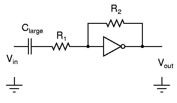
Determine the gain of the amplifier in (a) when the transconductance of the inverter tends to infinity. Build the amplifier in (a) with an ideal gain of 2 and R1 in 5kΩ to 10kΩ range. Use a 6V supply for this experiment. Measure the gain error. Connect inputs of unused inverters to ground
Apply a (small) squarewave and measure the step response. Is there an overshoot/ringing?
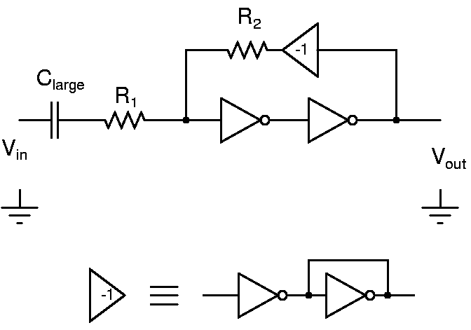
The gain error can be reduced by increasing the loop gain. Use another inverter in cascade (and a unity gain inverter for negative feedback) as shown above and measure the circuit. Does it result in a better amplifier? Apply a (small) squarewave and measure the step response. Is there an overshoot/ringing?
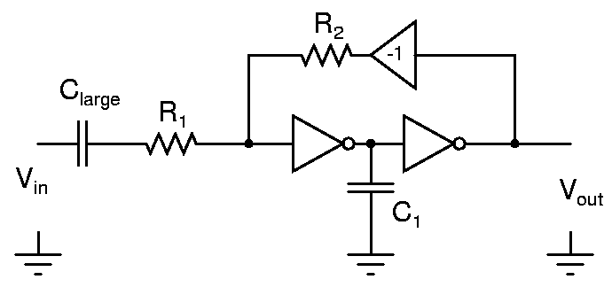
Compensate the amplifier by connecting a capacitor C1 to ground as shown above. Adjust its value for 10% overshoot. Use a 100mVpp square wave input for this measurement. While choosing the compensation capacitor, start from small values, of the order of 100pF.
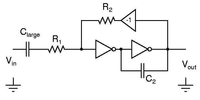
Compensate the amplifier by connecting a capacitor C2 across the second stage as shown above. Adjust its value for 10% overshoot. Comment on the compensation capacitor values C1 and C2 in the two cases. While choosing the compensation capacitor, start from small values, of the order of 100pF.


