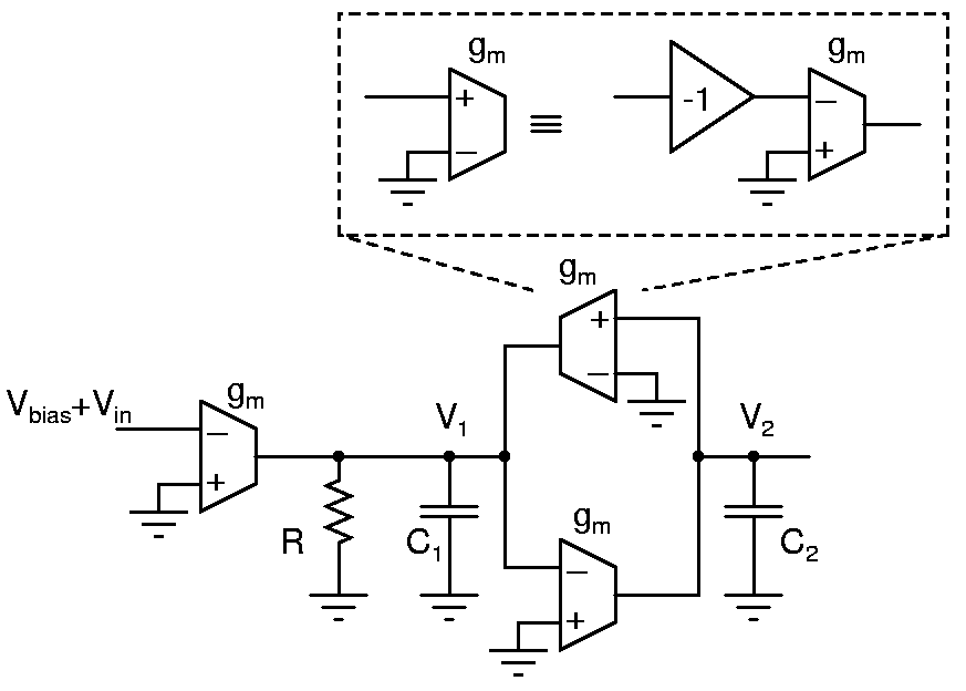
gm-C filter
Design the gm-C filter shown above for a resonant frequency of 5kHz and a quality factor of 2. Determine the transfer functions between the input and V1 and V2. Build the filter using only transconductors and capacitors. i.e. the resistor and the positive transconductor should be realized using only the inverters available on a 4069.
Measure the circuit and verify that it realizes the transfer functions given above. Filters can be measured by injecting sinusoidal inputs and observing inputs and outputs on 2 channels of an oscilloscope. Also, the phase difference between input and output can be gauged from X-Y plots, and the center frequency determined. Observe the step response by injecting a low frequency square wave to the filter.
Tune the filter using the power supply voltage and verify that it tunes as expected. The voltage Vbias at the input should be the bias voltage of the self biased inverter.
