Opamp amplifier
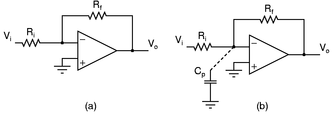
Design the amplifier in (a) for a gain of -10. What is the expected 3dB bandwidth? Measure the bandwidth by sweeping the input sinewave frequency. Is there peaking(gain at some frequency higher than the dc gain) in the frequency response? Measure the step response by applying a low frequency square wave. Is there an overshoot?
What happens when there is a capacitance from the inverting terminal of the opamp to ground? Connect larger and larger capacitors and see what happens to the step response and the frequency response. Explain.
Adjust Cp to get the largest bandwidth possible with no peaking in the frequency response. How does this bandwidth compare to the previous case? Explain clearly. Measure the step response and its overshoot, if any.
Using an inverter as a transconductor
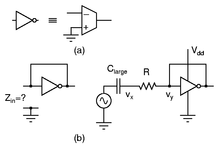
A CMOS inverter biased in its active region behaves like a transconductor ((a) in the above figure) with its positive input grounded. Determine the impedance of an inverter whose output is shorted to its input. Measure the transconductance by forming a voltage divider with this impedance and measuring the voltages vx and vy ((b) in the above figure). Do the measurements at 5V, 6V, and 7V supplies. Also note the dc bias voltage of the self biased inverter. How do these transconductance measurements compare to calculated values from the results of the first experiment?
Bias an inverter so that it can be used as a standalone transconductor (as in (a) in the above figure). The lowest input frequency can be assumed to be 100Hz.

