Logarithmic amplifier
Carry out all analyses before coming to the lab
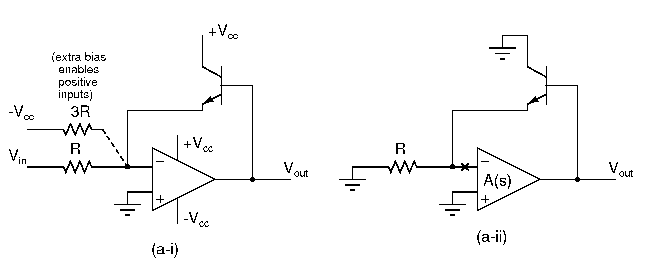
- Use Vcc=9V; Ignore the additional bias resistor of 3R initially
- Assuming an ideal opamp, and an ideal exponential transistor, determine the output Vout and the transistor current Ic in the circuit in (a-i). What is the range of Vin over which the circuit functions correctly?
- Modeling the transistor with a transconductance gm, determine the small signal loop gain of the circuit. You can break the loop at the inverting input of the opamp as shown in (a-ii), and assume that the opamp's gain is A(s).
- Does the loop gain depend on the input voltage Vin?
- Build the circuit and verify the functionality determined above. Apply a 1kHz square wave input varying between -0.25V and -2.5V and observe the output.
- Connect the additional bias resistor and observer the output with bipolar inputs? What is the largest allowable input amplitude?
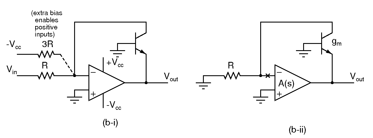
- Use Vcc=9V; Ignore the additional bias resistor of 3R initially
- Assuming an ideal opamp, and an ideal exponential transistor, determine the output Vout and the transistor current Ic in the circuit in (b-i). What is the range of Vin over which the circuit functions correctly?
- Modeling the transistor with a transconductance gm, determine the small signal loop gain of the circuit. You can break the loop at the inverting input of the opamp as shown in (b-ii), and assume that the opamp's gain is A(s).
- Does the loop gain depend on the input voltage Vin? What does it mean for the stability of the circuit?
- Build the circuit and verify the functionality determined above. Apply a 1kHz square wave input varying between +0.25V and +2.5V and observe the output.
- Connect the additional bias resistor and observer the output with bipolar inputs? What is the largest allowable input amplitude?
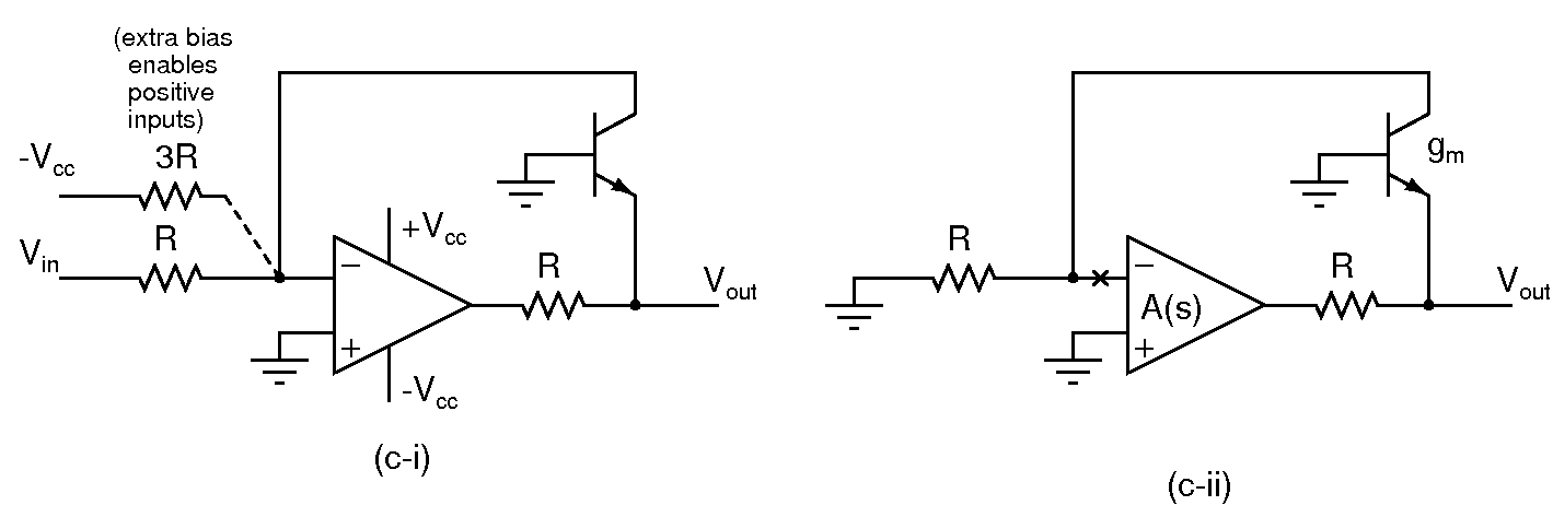
- Use Vcc=9V; Ignore the additional bias resistor of 3R initially
- Assuming an ideal opamp, and an ideal exponential transistor, determine the output Vout and the transistor current Ic in the circuit in (c-i). What is the range of Vin over which the circuit functions correctly?
- Modeling the transistor with a transconductance gm, determine the small signal loop gain of the circuit. You can break the loop at the inverting input of the opamp as shown in (c-ii), and assume that the opamp's gain is A(s).
- Does the loop gain depend on the input voltage Vin?
- Build the circuit and verify the functionality determined above. Apply a 1kHz square wave input varying between +0.25V and +2.5V and observe the output.
- Connect the additional bias resistor and observer the output with bipolar inputs? What is the largest allowable input amplitude?


